An Intro to Physically Based Rendering for Artists and Programmers - Part 1
Note: All figures in this article are from the book Real-Time Rendering, reused under Fair Use
Physically Based Rendering is a broad term that could potentially mean many different things depending on the exact context in which it is being used, but the defining characteristic is that there is an attempt being made to emulate or approximate real, physical processes as closely as is practical to create an image.
Most commonly, this refers to a set of asset creation and lighting workflows which define material and light properties based on real-world characteristics. The most common of these is called the "metalness" workflow and it uses three properties to define the characteristics of a material:
- Metalness
- Roughness/Smoothness
- Albedo
But, where do these come from and what do they actually mean?
#An introduction to the physics of light
The simplest way to start is by thinking about a single ray of light. We'll begin by thinking baout what happens to this ray if it passes through a "participating medium." A participating medium is just a field of particles that our ray of light is passing through, each of which are large enough to interact with the ray of light if they happen to come into contact. There are two things that can happen when the light intersects with a particle in the medium.
First, it can be "attenuated," which means that the ray's "wave function," which we think of as its "color," may be changed. Think about light passing through a colored but clear liquid like wine.
Second, it can be deflected or scattered, causing the single ray to be split into multiple rays in different directions. The more scattering that occurs, the "cloudier" a medium will appear. Think about clear water vs. ocean water vs. milk, clear water having the least scattering and milk having the most.
The next thing we will talk about is what happens when light his the border between two different participating mediums. This could be light traveling through air entering water, or light traveling through air "impacting" (in reality, entering) a solid object with some material. When this ocurs, the light is split into two directions, the direction of reflection and the direction of refraction.
If we observe the border between two mediums as a flat plane pointing up as below, we can see the light impact the 'surface' between them at a point. We can see the direction of the light source `l`, and the corresponding reflection and refraction vectors, `r_i` and `t`. `r_i` is reflection and `t` is refraction, labelled as such because refraction can be thought of as "transmitted" light, so we call this vector t for transmission. This transmission (refraction) vector is the direction in which light that continues into the new medium will travel, while the reflection vector is the direction in which light that simply bounces off the surface (the border of the two mediums) will travel. We can also see the surface normal, `n`, which is the direction that the surface is pointing.
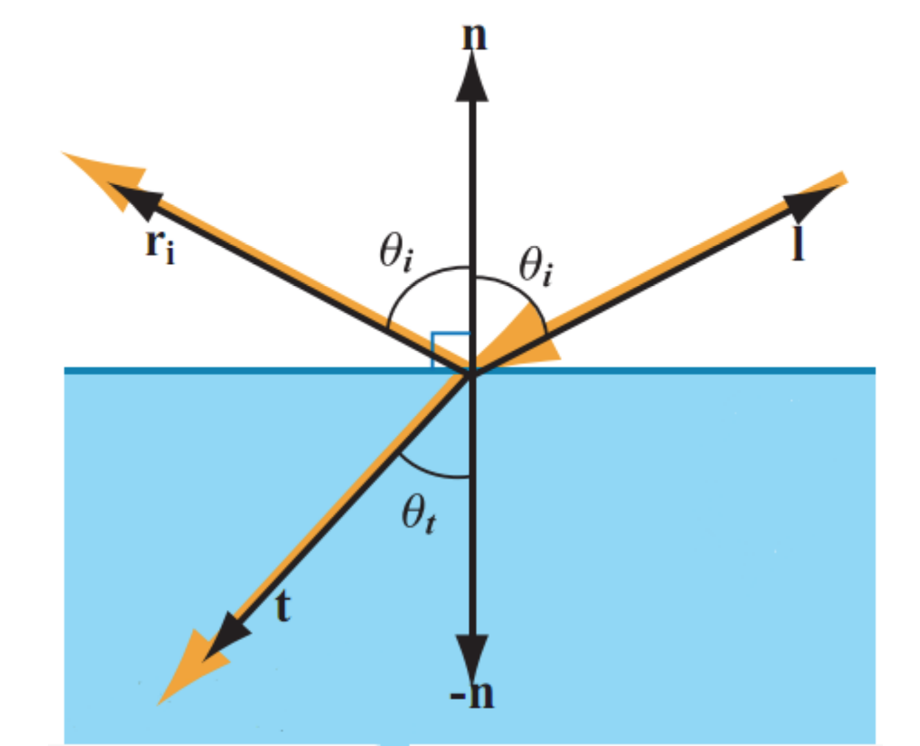
The direction of reflection is always the same, it is the direction in which you would intuit an object would "bounce" off the surface: the angle between the incoming vector and the surface normal and the outgoing vector and the surface normal are the same. The refraction direction, however, is dependent on something called the 'index of refraction' (IOR). Each medium has one of these, and the ratio between them determines the direction of refraction when a ray passes through the border between them. This is why light seems to bend when you look into water or through a glass (or most any transparent object, though some have more or less bend depending on their IOR and how it compares to the IOR of air).
The ratio between the portion of the power of the original light ray which is reflected and the portion which is refracted is determined by the Fresnel equations. You may have heard of this phenomenon referred to as the "Fresnel effect," and it is inherent to all surfaces. The exact equations are beyond the scope of this introduction, but we can visualize essentailly what is going on quite easily.
Imagine there is a baseline 'reflectiveness' of a surface, which is the ratio of the original ray's power which is reflected rather than refracted. Now imagine that this ratio increases towards 1.0 as the surface curves away from the incident light vector, so that at "grazing angles" (when the normal of the surface is perpendicular to the incident vector), almost all of the original ray is reflected rather than refracted. We can see that this has a very important effect on the look of objects, and while it is most obvious on materials like water, it happens even on materials like cardboard and brick. The remaining light which is not reflected is refracted and begins to be ransmitted through the new medium, just as we discussed above.
The final piece of the puzzle here is that what we mean by "power" is actually the amount of light at different wavelengths, aka the color of the ray. Just as we discussed at the very beginning, when a ray of light is reflected or refracted, it may be attenuated (its color and power changed).
What we've discussed so far only applies to a perfectly smooth, very small section of the interface between two mediums, but this doesn't allow us to fully simulate what we want to be able to: real world surfaces at a more macroscopic scale. For this, we need something called "Mircofacet Theory," which builds upon the very basic interactions we've defined so far.
#Metalness
It turns out that we can generally group materials into two large categories and then apply a model called Microfacet Theory to simulate a very large range of real world materials quite accurately. First we'll talk about the two categories, which together make up the "metalness" piece of the "metalness workflow" we discussed at the beginning. These two broad categories are
- Metals (conductors)
- Dielectrics (non-metals, insulators)
- (Semi-conductors)
There are also technically semi-conductive materials like silicone, however there are very few, if any, of these materials which we see regularly on any object, so we generally ignore them.
The difference between these two types of materials (metallic and dielectric) has to do with what happens to the refracted (transmitted) light we discussed earlier.
In metals (conductors), there are many extra, free "valence" electrons available in the atoms of the material. This means that the refracted light which enters the medium of a conductive material are quickly absorbed and so never escape the material again.
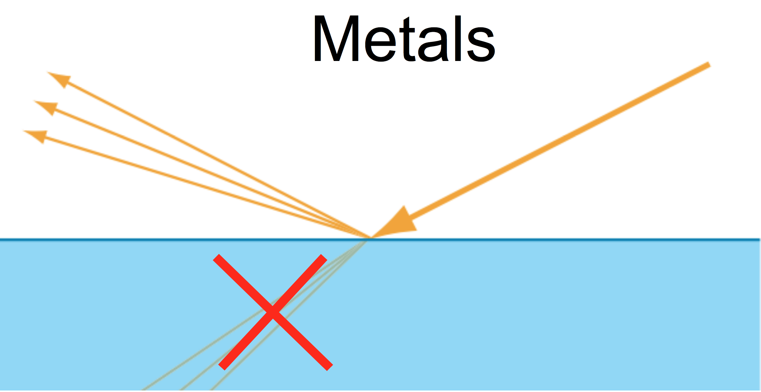
Therefore, only the part of the incident light which is directly reflected will escape. Metals generally have much higher reflectance than dielectrics (the ratio of reflected light at non-grazing angles), and will often attenuate the reflected light to give it a tint which we think of as the "color" of that metal. This is why you may have observed or been taught that metals have tinted specular highlights. In reality, metals are only specular highlights, as the only light that leaves the surface is the directly reflected light (what is often thought of as "specular").
In dielectrics (non-metals, insulators), there is not an excess of free elecrons to absorb the transmitted light, and so that refracted light continues into the new medium and the "scattering" process that we discussed at the very beginning for light passing through a particiating medium is allowed to take place. For 'solid' materials, the amount of scatering is very high, and the amount of attenuation is also quite high, so the light does not penetrate very far. However, it does penetrate far enough to scatter, be attenuated by pigment or other colored particles inside the material, and then be ejected back out from the surface.
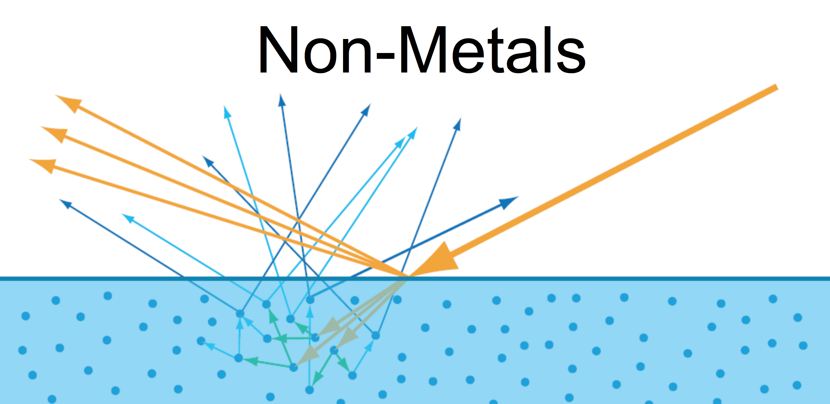
This creates the traditional "diffuse" style lighting actually comes from, and it is called "subsurface scattering." You may have heard of a special kind of material or shader which uses subsurface scattering. The only difference between tradional "diffuse" scattering and this effect which so often gets called "subsurface scattering," is the scale at which the scattering happens. If a ray of light will enter the surface, be scattered, and then re-emerge from the surface all within an area smaller than what will become one pixel on the screen, then we get a "diffuse lighting" effect. If, on the other hand, a ray of light can enter the surface, be scattered, and then reemerge somewhere else (from a different pixel), then we need a different, more complex algorithm to try to mimic that, and that is why we have special "subsurface scatering" shaders.
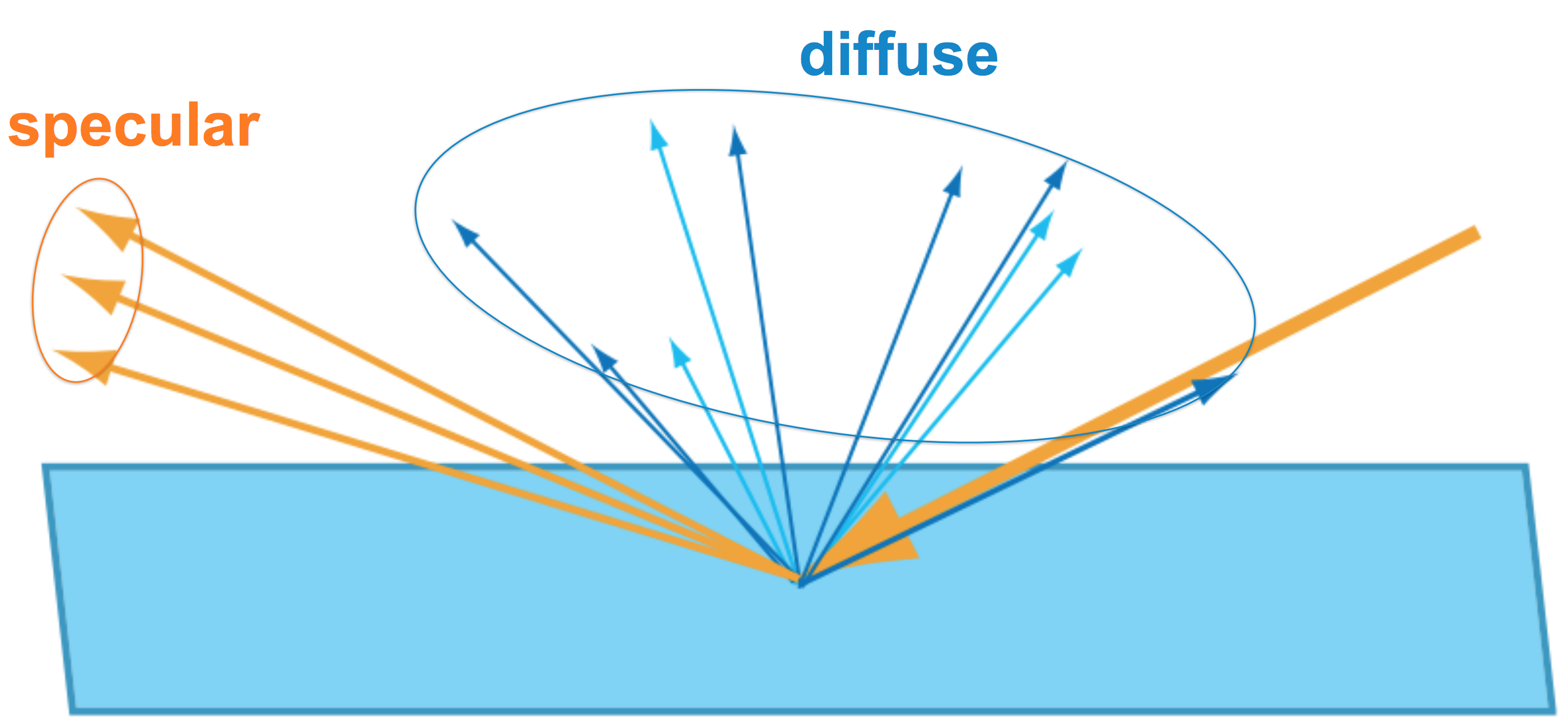
For non-metals, the reflectance at non-grazing angls is much lower than for metals (except in some special gems like diamond) and is not colored. This is because the coloration of dielectric materials comes from some kind of pigment buried a few layers deep in the material. Therefore, the top layers, which have the potential to actually reflect light instead of scatter the transmitted light, are actually not colored and do not significantly change the color of the light they reflect. This is why dielectrics almost always have un-tinted, pure-white specular highlights, unlike metals.
Alright, that's all for this blog post. Next time, we'll get into Microfacet Theory, the final piece of the theory-puzzle for PBR and which is what the "roughnes" part of the metalness workflow comes from.
Latest Posts
- The plight of the misunderstood memory orderingRust Atomics and Locks, the Rustonomicon's page on atomics, much of the standard library's documentation, and many more sources already…read more →
- (Nurturing) The Soul of a Computer EngineerA love letter to myself, to computers, and to the culture that surrounds them I was brought to tears while walking to work this morning.…read more →